-
Product Description
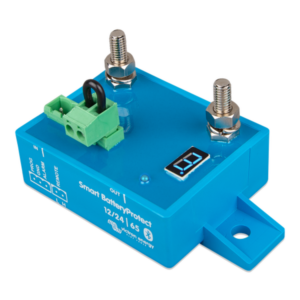
Protect your batteries from accidental excessive discharge by installing a BP65 between your battery positive and DC distribution buss or fuse box. For loads under 65A.
The Battery Protect is designed to keep your battery safe and only allows current to flow to DC loads on the output when the voltage is in a safe range. In systems with larger loads/ inverters, it may not be possible to both properly protect your battery and run demanding loads without having the Battery Protect temporarily disconnect DC loads. You can easily adjust the BP cutout voltage to meet your application from the Victron Connect app at any time to find that fine line between protection and not having nuisance tripping. AM Solar is not responsible for misuse of the product resulting in damaged batteries.
-
Operation
The BP65 is a programmable MOSFET that can handle up to 65A of continuous load current and surges up 300A (100A and 220A models are also available). When properly programmed, the BP65 acts as a switch that opens (turns off loads) when the battery bank voltage drops below a certain threshold. When the battery gets recharged, above a certain threshold it reconnects.
When a low voltage is detected, there will be a 90-second delay before the load is disconnected. This prevents loads with a startup surge from accidentally triggering the device. When a battery is recharged, there is a 30-second delay before the load is reconnected after the restart voltage threshold has been crossed.
The remote jumper can be configured as a disconnect switch.
-
Installation
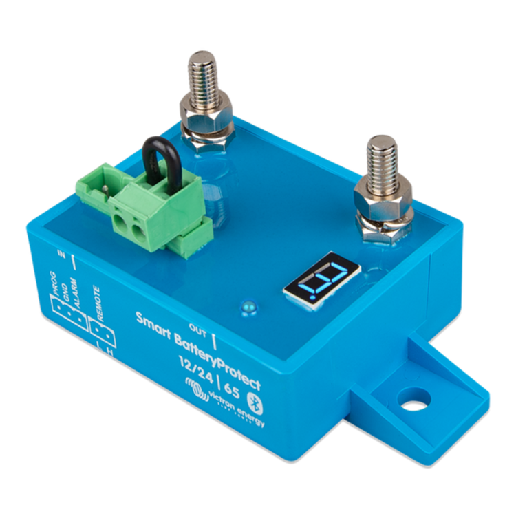
Install the BP65 between the battery bank positive and the DC load buss or fuse box with the IN post on the battery side and the OUT post going to the loads. Do not connect to the OUT post until the BP65 is programmed. Connect the black wire from the GND pin to the battery negative post or chassis. Install a fuse or breaker (with a rating under 65A) between the BP65 and the battery.
-
Programming
1) Supply 12V power to BP (+ to IN post, – to GND pin). When a voltage is detected the top and bottom bar of the numerical display will flash.
2) Remove the remote port plug (2 pin green terminal block with jumper).
3) Connect PROG pin to -, GND, or chassis using a wire scrap.
4) The display will begin cycling through the numerical values corresponding to different connect/reconnect voltages shown in the instruction manual.
5) Once you see the desired setting remove the scrap wire from the PROG pin. (6 is a common choice with a disconnect at 11.5V and a reconnect at 12.8V.)
6) When the program mode is selected the display will flash between the mode number and a letter representing the relay function.
7) After the display goes blank connect the PROG pin to -, GND or chassis again. The display will begin cycling through the alphabetical Relay function options. Choose “b” for Relay protection mode.
8) Once you see the desired setting remove the ground from the PROG pin. The device will display the current settings.
9) Connect the DC Loads to the OUT post. Your batteries are now protected
What our customers are saying
There are no reviews for this product yet. You can be first.
The am solar way
-
Treat customers right
-
Treat each other right
-
have fun
-
build a strong business