Disclaimer: While the message of this blog may be applicable to a wide variety of charge controllers, this article pertains specifically to Victron SmartSolar MPPT solar charge controllers. We feel these are the best solar charge controllers on the market. Our business model is built around providing free, lifetime support for our clients, and as a result, we have to be very particular in the products we recommend. To learn more about Victron charge controllers and see their specifications, click here.
Critical Considerations
Don’t damage anything:
If you are designing a solar power system, you probably know that a solar array delivers power to a charge controller and that charge controller reformats this power into something that can be used to charge a battery bank. This power from the solar array can be measured in terms of voltage and current. As long as you don’t exceed the voltage and current limits of the charge controller you won’t hurt anything.
Charge a battery bank:
If you aren’t damaging anything, and you have at least a 5V differential between the operating voltage of the solar array and the battery bank, you’ll have a system that is capable of charging a battery bank.
Make it efficient:
Lastly, if you keep your array wattage times 90%, divided by the nominal voltage of the battery bank, under the current rating of the charge controller, (propper array to charge controller output) you’ll have an efficient system. 400W x 0.9 / 12V = 30A
It’s that simple…
Staying Within Tolerances
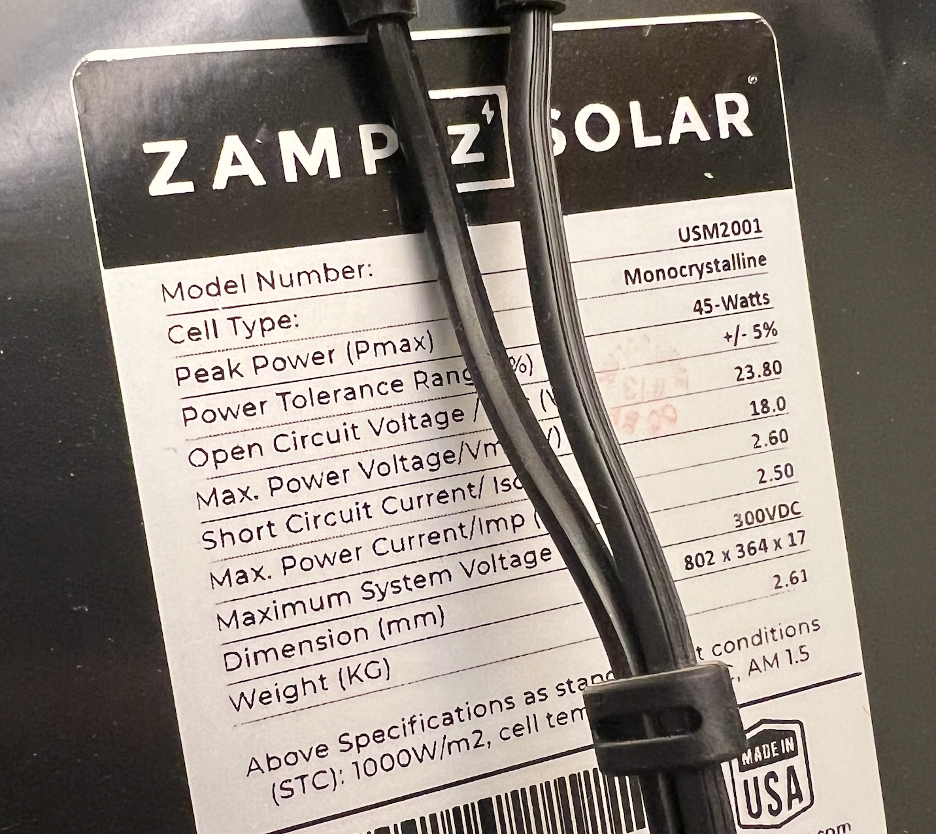
When verifying that your solar array input current and input voltage to the charge controller are within tolerances, you need to look at the Current Short Circuit (Isc) and Voltage Open Circuit (Voc) of the solar array. This is easy if you have just one panel in your array, these values will be listed in the specifications sticker on the back of the panel. With multiple panels, you will need to add Voc for series connections, and add Isc for parallel connections.
For example, say you have four panels, each with a Voc of 25V, and an Isc of 5A, you will get the following array specifications:
All-series: Voc: 100V, Isc: 5A
All-parallel: Voc: 25V, Isc: 20A
Series Pairs (2 x 2): Voc: 50V, Isc: 10A
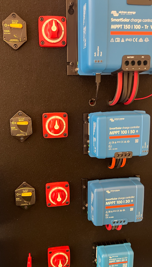
This Voc number is so important that it is the first number you see in the part number of a Victron SmartSolar MPPT charge controller. For example, the 100/30 charge controller can handle an open circuit array voltage of 100V. The 150/100 charge controller can handle 150V.
Issues with Isc come up very infrequently with 12V battery banks, but we do bump into it occasionally with the 150/70 model (50A Isc) and the 150/100 model (70A Isc). This happens when you try to max out these charge controllers with parallel arrays of large 36-cell panels that have an Isc over 10.0A. Specifically, you can’t have seven or eight 190W panels in parallel on a 100A charge controller because you will exceed the Isc limit.
Voltage Differential
This comes up very infrequently with 12V systems, and you’ll want to make sure the Vmp (Voltage at maximum power) of the array exceeds your nominal battery bank voltage by at least 5V. A voltage that is well above this, but within the Voc limit of the charge controller won’t damage anything, but it also won’t result in a performance increase. There is some wiggle room in this formula, and people have had success with 17.7Vmpp panels on 12V battery banks, but we prefer to keep the array over 18V. That means if you have a 24V system, you need an array with a Vmp greater than 36V. With standard, 36-cell solar panels, this means you’ll need some series connections when charging a 24V battery bank. If you have 18Vmp panels, you won’t want to connect them in parallel for a 24V battery bank.
Efficient Design
By “Efficient” I’m referring to avoiding situations where you have way more solar wattage on your controller than it can process, resulting in clipping. For example, if you have a Victron 100/30 charge controller, you can connect it to six 200W panels (1200W), with the panels configured in two parallel groups of three in series. You won’t exceed the Voc or Isc limits. But, there’s no way the charge controller is going to be able to fully utilize that entire 1200W of solar when it is exposed to bright sunlight. A 1200W array has the potential to deliver about 90A of charging current to a battery bank. But that 100/30 controller is going to clip off everything beyond 30A. A solar charging system like this would only be used in very high latitudes or areas with extremely cloudy weather.
To check the efficiency of your array, use the following formula:
Array Wattage / Battery Voltage x Efficiency = Charging Current
Wattage – Sum the wattage of all the solar panels in your array. It doesn’t matter if you plan to connect panels in series or parallel, the wattage stays the same. With an MPPT charge controller, only the Voltage x Current of the solar array is proportional to Voltage x Current of the MPPT charge controller’s output. In other words, just because your solar array current (Imp) is 10A, doesn’t mean your charge controller output will be 10A.
Voltage – This will either be 12V or 24V in an AM Solar system. Even though you may have a 12.8V nominal lithium battery bank, just round to 12V. Remember, this is just an approximation. Exact numbers are only required when dealing with Voc and Isc limits.
Efficiency Factory – We use 90% and this accounts for line losses, less-than-perfect weather conditions, and a charging voltage slightly higher than the nominal voltage. This is reasonable for pretty much any application under about 50 degrees of latitude. If you get closer to a pole, use a lower number.
For example, if you have room for two 200W solar panels, and a 12V lithium battery bank, the math works out like this:
2x 200W / 12V x 0.9 = 30A
Two 200W panels is the most you would want to put on a 30A charge controller.
This formula has wiggle room, and they are summarized below with a charge controller vs. solar wattage recommendations.
15A < 230W
20A < 300W
30A < 450W
50A < 700W
85A < 1200W
100A < 1400W
But what about…
What If my array has too much/too little wattage?:
If you graph the wattage output of a solar array over time from morning to night, you will see a bell curve distribution, with a peak at mid-day. If you have a solar array that doesn’t exceed the Voc or Isc limit of the charge controller, but is capable of producing more power than the charge controller can pass, you will get output clipping. This doesn’t harm the charge controller, it just gives you a bell curve with a flat peak.
An example of this would be four 200W panels on a 100/50 charge controller. On a very bright day, an 800W array might be able to feed 60A onto a 12V battery bank, but if you use the 100/50 charge controller, it will be limited to 50A. The 10A that could be, with a larger charge controller, isn’t dissipated as heat, it just doesn’t exist, because the charge controller draws power at a less efficient point along the IV curve in order to keep from overloading. If you don’t know what I’m talking about in terms of the “IV curve” I have a video on that.
Along similar lines, if you have an undersized solar array, or oversized charge controller, this is perfectly reasonable. Think about what happens at night, or early morning, or late evening. …It’s the same thing. We design many of our systems this way, to give our clients room to expand if they want to enlarge their solar array.
What about during temperature extremes?:
A question that came up a few times in the YouTube comments on my last video was “What about low temperatures raising the voltage beyond what the charge controller can handle?”
For us, we recommend parallel connections, or maybe two panels in series at the most, so we are typically nowhere near the input voltage limit of the charge controller. But, I can go over a scenario showing how this would work.
Let’s say you have four 200W panels that you want to put in series on a Victron 100/50 charge controller, and the Voc of the panels is 24.35V with a temperature coefficient of Voc of -0.30% per degree C.
At a cell temperature of 25 degrees C, the Voc of the array is 97.4V and the charge controller is rated to handle 100V. If you go down 1 degree C, the Voc will go up 0.30%. That means, at 24 degrees C, you will have a Voc of 100.3V. I don’t think Victron is going to warranty an operator error like that. If you are close to the Voc, (within 10%) it might be worth running some calculations to see how close you get when it is really cold.
What if I put my panels in all parallel/all series, won’t I get more output?
Power (Wattage) is Volts x Amps, and an MPPT charge controller just shifts the balance of volts and amps, while maintaining wattage (minus efficiency). Since the voltage output, what is needed to safely charge the battery, is controlled based on battery chemistry, shifting the balance of volts and amps that the solar charge controller sees as input will not affect the output current of the charge controller. Put more simply, if you order a 16” pizza, you still get the same amount of pizza if it comes in four or eight slices. Unless you are overcoming partial shading, or some serious line losses between your solar array, you will not get a better charge by putting more panels in series/parallel. This is irrelevant.
Lastly, if you want help selecting the correct charge controller, tell us the quantity, make/model of your solar panels, and we’ll be happy to help.